Metal plays a vital role in every working environment and household. It has proven useful in a wide range of applications, affecting how people operate. From appliances to fixtures, utensils, and tools, metal continues to make every one of today’s conveniences possible.
Sheet metal fabrication refers to the umbrella term that encompasses the processes used in building machines and structures from sheet metal. These processes use flat metal sheets as raw materials and turn them into valuable products. Generally, custom metal fabrication turns raw metals into pre-made shapes for use.
Fabricated sheet metal is critical and common in multiple industries worldwide, including electronics, automotive, aerospace, telecommunication, and energy industries. This process has such wide popularity due to its ability to build many different structures from raw sheet metals. Its applications also grow each day due to increased accessibility and economics.
Contents
What Is the Metal Fabrication Process?

The custom metal fabrication process involves several different steps. It is crucial to understand how fabrication works for maximum productivity. Sheet metal fabrication often involves the following procedures:
- Cutting. This is the most commonly used fabrication process. This process involves the splitting of sheets of metals into halves, thirds, or even smaller sections. In several applications, the fabricator cuts freshly made metal that hasn’t been made into any shape. Some other applications involve the use of pre-shaped metals such as measured panels and bars.
- Folding. In this process, the fabricator manipulates the metal surface to shape at different angles. Some folding applications intend to fold the metal surface at a 90-degree angle. It may also be at other angles to make it either less or more blunt.
- Welding. Just as cutting, welding is a standard process in custom metal fabrication among enthusiasts. This process involves joining two or more separate metal parts. The parts could be sheets, bars, panels, or other shapes of metals.
- Machining. It involves the removal of portions of metal from the whole piece to create the desired process. Many manufacturers carry out this process on a lathe. However, there are several improved machines and tools today for the machining of sheet metals.
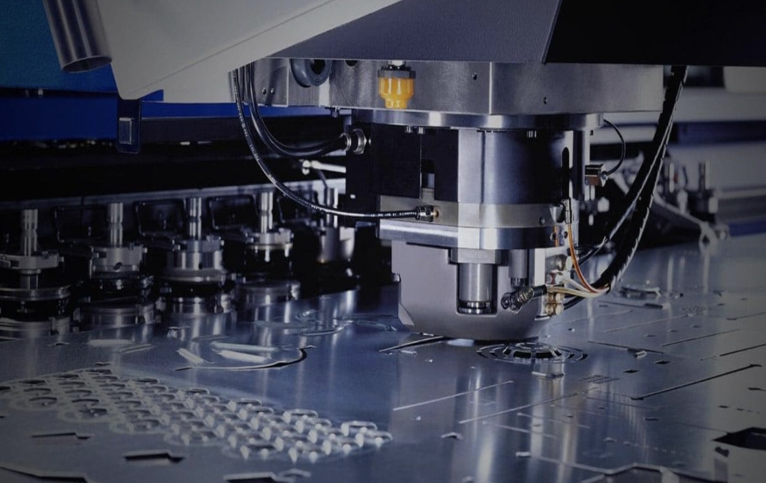
- Punching. The process that involves the formation of holes on a piece of metal is punching. In this process, metals are placed under a die, and a drill helps with the punch-through process. The aim, many times, is to create holes on the metal to allow fastening latches and other parts.
- Shearing. This process involves creating long cuts on sheets of metals. It may involve the vertical application of the cutting tool against the flat metal sheet. Another standard method is the horizontal feeding of the sheet through a metal-cutting machine. Shearing helps to trim the edges of metal sheets.
- Stamping. In applications with no requirement for holes, stamping is used to raise certain parts of the metal sheet without penetrating it. It helps to form specific shapes, images, or letters within the metal material.
- Casting. Although vintage, casting remains a flexible method of metal fabrication. It is an ideal method for making several complex shapes in prototyping services. In many cases, it offers manufacturers easy solutions to metal fabrication problems. It is suitable for several metals, including steel, copper, magnesium, iron, and silver.
Following DFM Guidelines for Sheet Metal Fabrication
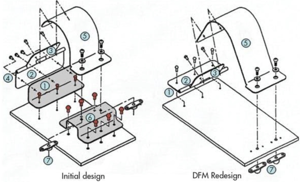
As previously mentioned, sheet metal fabrication involves several processes such as cutting, folding, punching, etc. While these processes can be pretty accurate, they create room for errors. These errors may compromise the quality of the final product. Following DFM guidelines is an efficient way to start your sheet metal fabrication.

DFM (Design for Manufacturing) guidelines help to ensure the accurate reproduction of a design using available technology. This engineering philosophy takes to account the limits of the currently available manufacturing capabilities. Some shapes might look easy on the eye and a CAD program, but they are not always straightforward during manufacturing. Therefore, it is essential to follow the following DFM guidelines for custom metal fabrication:
- Wall Thickness: Generally, maintaining a uniform wall thickness across the entirety of the design is best practice. It is crucial to avoid thin walls, deep pockets, and areas that could bend easily under pressure or stress.
- Bend Relief: Bend reliefs are essential in metal fabrication. They help to avoid torn metal, and they prevent metals from cracking or snapping under pressure. They also add stiffness to the final product and reduce spring-back effects.
- Hole Sizes: Hole diameters should never be lesser than the sheet thickness to prevent high punch loading. This will also prevent the formation of burrs and burnishes on the finished product.
- Hole Location: Spacing between holes is also very significant. Holes should be at least two thicknesses away from each other. The holes should also be placed at least one thickness from the edge. If there must be a hole near a bend, it should be 1.5 thickness away from the bend radius.
- Tolerance: Tolerances should be stated at the start of the fabrication process to prevent wastage, increased cost, and compromised final product.
- Punch-to-Die Clearance: Small clearances often increase burr height and may wear out the punch prematurely. Therefore, it is essential to factor in clearance between the hole punch and the die that keeps it in place. The overall aim is to limit manufacturing costs and give a smooth final product.
- Grain Structure: This structure helps avoid cracks in parts with tabs or lugs bent in or out. Tabs and lugs created parallel to the grain tend to tear under pressure. Therefore, it is important to place the lugs at perpendicular angles or an angle less than 45-degree towards the direction of the grain.
- Corners and Points: It is important to avoid sharp corners at all costs. Engineers should also try to avoid unnecessary points. These areas are usually the first to break whenever the component is under pressure.
Significance of DFM in Sheet Metal Fabrication
Engineers and designers who adhere to sheet metal fabrication DFM guidelines create high-quality metal products at reduced costs. The possibilities of errors on these products are also significantly reduced. The following are advantages of DFM in sheet metal fabrication:
Reduced Cost
Generally, following DFM guidelines minimizes part counts. This, in turn, encourages ease of assembly. There is also reduced waste and ease of manufacture. All these combine to reduce the total manufacturing cost.
Retained Product Quality
With a simplified process and the right guide for design, it becomes easy to design parts that meet clients’ expectations. These parts come out with the highest quality, and they meet desired requirements.
Faster Production
DFM guidelines for sheet metal fabrication ensure that specifications ensure ease of production. Straightforward processes furthermore ensure faster production of parts for a shorter time to market.
Lesser Mistakes During Production
When engineers meticulously follow DFM guidelines, they tend to make fewer mistakes during part production. This helps to prevent wastage and contributes to reduced manufacturing costs.
